Uncategorized files
Jump to navigation
Jump to search
Showing below up to 100 results in range #1 to #100.
View (previous 100 | next 100) (20 | 50 | 100 | 250 | 500)
 0002 Alt Temp Sense Bolt.jpg 500 × 375; 73 KB
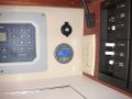
 0010 Ext Reg Display View.jpg 500 × 375; 80 KB
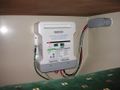
 0014 SmartPlug Installed.jpg 1,024 × 768; 240 KB
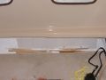
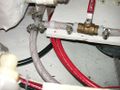
 0028 Hose Chafe Guard.JPG 2,560 × 1,920; 1,003 KB
 0028 Hose Chafe Guard (resized).jpg 500 × 375; 81 KB
 01-epoxy-mold-installation.jpg 640 × 480; 51 KB
 02-epoxy-mold-installation.jpg 640 × 480; 52 KB
 027.JPG 735 × 801; 416 KB
 03-epoxy-pad.jpg 768 × 512; 38 KB
 04-gouger.jpg 768 × 512; 32 KB
 05-crap-catcher.jpg 768 × 512; 16 KB
 06-hole-reinforcement.jpg 768 × 512; 30 KB
 0618 90 Degree Drill Adaptor.jpg 1,024 × 768; 199 KB
 0618 Breadboard.jpg 1,024 × 768; 238 KB
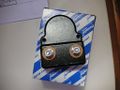
 0618 Conversion Kit PN.jpg 1,024 × 768; 166 KB
 0619 Breadboard Bonding.jpg 1,024 × 768; 225 KB
 0619 Conversion Kit Complete Top View.jpg 1,024 × 768; 244 KB
 0620 New Shelf In Work).jpg 500 × 375; 49 KB
 0621 Conversion Kit Complete Inside View.jpg 1,024 × 768; 185 KB
 0622 Wire Tie Mounts.jpg 1,024 × 768; 261 KB
 0623 Eng Control Panel Wire 50.jpg 1,024 × 768; 286 KB
 0625 House Bank Test Fit.jpg 1,024 × 768; 303 KB
 0625 House Fuse Block.jpg 1,024 × 768; 268 KB
 0626 OEM AC Terminal Strip.jpg 1,024 × 768; 288 KB
 0627Battery Box Eggcrate.jpg 1,024 × 768; 248 KB
 0627 Installed House Bank.jpg 1,024 × 768; 324 KB
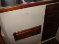
 0627 New Teak Fascia.jpg 500 × 375; 52 KB
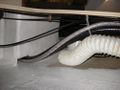
 0627 Wiring Run Under Macerator.jpg 500 × 375; 63 KB
 0628 Old Teak Fascia.jpg 500 × 375; 47 KB
 0630 Wires Exit Conduit Near Heater.jpg 1,024 × 768; 258 KB
 0632 House Bank Vents.jpg 1,024 × 768; 262 KB
 0633 New Vents and Battery Switch.jpg 500 × 375; 55 KB
 0635 Battery Box Cable Entry.jpg 500 × 375; 53 KB
 0636 Main Cables to Battery Switch.jpg 1,024 × 768; 283 KB
 0638 Always On Busbar.jpg 1,024 × 768; 306 KB
 0639 Alt Out and Fuse Block.jpg 1,024 × 768; 306 KB
 0642 Cables Entering Battery Compartment.jpg 1,024 × 768; 224 KB
 0643 Main DP Installed.jpg 1,024 × 768; 304 KB
 0643 Neg Leaves Battery Compartment.jpg 1,024 × 768; 239 KB
 0644 Neg Post Extension.jpg 1,024 × 768; 273 KB
 0645 House Negative Busbar.jpg 1,024 × 768; 271 KB
 0645 Reserve Cable Connects to Shunt.jpg 1,024 × 768; 271 KB
 0646 BMV700 Shunt Installed.jpg 1,024 × 768; 302 KB
 0646 BMV700 and 12VDC Outlet.jpg 1,024 × 768; 277 KB
 0646 House Negative Connects to Shunt.jpg 1,024 × 768; 302 KB
 0646 House Ngeative Connects to Shunt.jpg 1,024 × 768; 302 KB
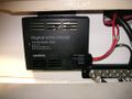
 0647 Charger Front.jpg 1,024 × 768; 259 KB
 0647 Echo Charge Installed.jpg 1,024 × 768; 243 KB
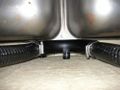
 0648 New Cables By Water Tank.jpg 1,024 × 768; 263 KB
 0649 Fridge Coil Protector.jpg 1,024 × 768; 228 KB
 0652A New Cables Between Heater and Battery Box.jpg 1,024 × 768; 203 KB
 0653 Foam Pad on Corner Heater Support.jpg 1,024 × 768; 264 KB
 0655 New Shelf At Fridge Compressor.jpg 1,024 × 768; 258 KB
 0657 Reserve Battery Clearance.jpg 1,024 × 768; 253 KB
 0659 New Cables Exit By Foot Pump.jpg 1,024 × 768; 216 KB
 0663 Wires In Wet Locker.jpg 1,024 × 768; 218 KB
 0664 Reserve Battery Fuses.jpg 1,024 × 768; 291 KB
 0667 Reserve Battery Negative Post Access.jpg 1,024 × 768; 240 KB
 0668 Reserve Battery and Small Tool Bag.jpg 1,024 × 768; 262 KB
 0672 New Cables Under Prop Shaft.jpg 1,024 × 768; 282 KB
 0676 New Cables Tie Wrap By Water Hose.jpg 1,024 × 768; 255 KB
 0678 Battery Box Vent Seal.jpg 1,024 × 768; 217 KB
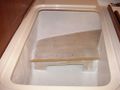
 0680 Ext Reg Wires Into Conduit Under Shower Pan.jpg 1,024 × 768; 191 KB
 0682 Ext Reg Wires To Shower Pan.jpg 1,024 × 768; 314 KB
 0685 Charger Temp Sense Phone Coupler.jpg 1,024 × 768; 181 KB
 0686 Wires Run Under Macerator To Bilge Area.jpg 1,024 × 768; 322 KB
 07-unpainted-pad.jpg 768 × 512; 37 KB
 0705 Reserve Battery Wire Runs.jpg 1,024 × 768; 305 KB
 0706 Breadboard Installed Complete.jpg 1,024 × 768; 167 KB
 0707 Wires Leaving Behind Main DP.jpg 1,024 × 768; 211 KB
 0708 New Cables Routed Toward Heater.jpg 1,024 × 768; 256 KB
 0715 Charger and Nav Station Desk.jpg 1,024 × 768; 241 KB
 0716 New AC Terminal Strips.jpg 1,024 × 768; 360 KB
 0716 New AC and DC Term Strips.JPG 2,560 × 1,920; 1.02 MB
 0716 New AC and DC Term Strips (resized).jpg 500 × 375; 82 KB
 0718 Main DP Back AC Breakers.jpg 1,024 × 768; 380 KB
 0719 Ext Reg Conduit Loom.jpg 1,024 × 768; 319 KB
 0719 Main DP Back DC Breakers.jpg 1,024 × 768; 447 KB
 08-shop-vac-boat-version.jpg 768 × 512; 35 KB
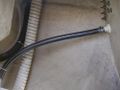
 1.12 Hose After Vented Loop resized.jpg 500 × 375; 71 KB
 1.12 Hose To Vented Loop resized.jpg 500 × 375; 63 KB
 1.12 Hose check valve and manual pump.jpg 500 × 375; 61 KB
 1.12 Upper Transom Thru Hull resized.jpg 500 × 375; 58 KB
 1.12 Vented Loop Screw resized.jpg 500 × 375; 47 KB
 1.12 Vented Loop Top Sink resized.jpg 500 × 375; 52 KB
 1.12 and Aft Water Tank Revised.jpg 500 × 375; 64 KB
 1.12 transom thru hull.jpg 500 × 375; 53 KB
 1.5 Hoses Away From Seacock resized.jpg 500 × 375; 83 KB
 1.5 Hoses Exiting Aft Cabin Revised.jpg 500 × 375; 59 KB
 1.5 Vented Loop 2 resized.jpg 500 × 375; 65 KB
 1.5 Vented Loop resized.jpg 500 × 375; 74 KB
 10-capstan-fit-check.jpg 768 × 512; 37 KB
 107682452.xfxJjmEn-1-.jpg 106 × 160; 9 KB
 108349271.S6fMMWGT.jpg 530 × 800; 119 KB
 10AC-Yet-To-Be-14676.jpg 640 × 480; 36 KB
 10 M35b ready to mount with gasket.jpg 661 × 496; 41 KB
 10 Windlass solenoid starboard side.jpg 640 × 480; 46 KB
 10arthur.jpg 640 × 480; 61 KB
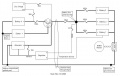 10schematic.jpg 933 × 592; 56 KB
 11-finished-pad.jpg 768 × 512; 45 KB


.jpg)


.jpg)


.jpg)


